
SCC 2026 HW CHALLENGE
`•.¸¸.•´´¯`••._.• 🪩 𝒊𝒏𝒔𝒕𝒓𝒖𝒄𝒕𝒊𝒐𝒏𝒔 🪩 •._.••`¯´´•.¸¸.•`
Hey there, it’s 𝕗𝕚𝕗𝕥𝕪 speaking.
Here are some instructions for the hardware challenge.
the box
Check the contents of the box. If you’re missing any of the following:
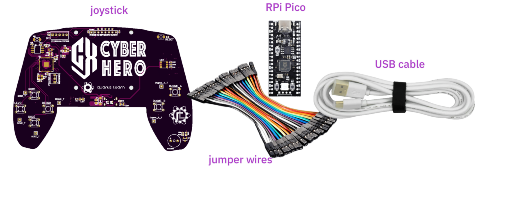
call me 😉
If the RPi Pico board is greasy, it’s either the soldering paste or Jovan (TheProxy) touched it while eating burek.
the joystick
1. Absolutely do not flash new firmware. If you flash new firmware or delete the contents of the flash memory, don’t call me.
2. The board operates at 5V. Use the provided USB cable to power it from your computer. At some point you might need two cables. In that case, use the provided cable for data transfer and your phone charger can be used to power the device.
3. While the device is booting, the RGB LED (on the right) blinks GREEN and the buzzer makes an annoying noise.
4. Once the boot process is complete, the RGB LED will turn BLUE and the buzzer will stop screaming.
5. Avoid touching the solder pads on the bottom side of the PCB during operation, as this may cause unexpected behavior.
6. To work with the joystick, you will need the PCB schematic (click to download).
7. SEEMS like the PCB can be powered through the additional RPi through the 3v3 pin. In that case, DON’T use both 3v3 and USB C power supply.
the display that does not exist
- 64×32 monochrome SPI display interface
- Bit-packed pixel encoding
- Stores pixels in a left-to-right, top-to-bottom format, with start and stop bit bounding
… good thing it doesn’t exist, who needs a display like this anyway?
P.S.
You can keep the hardware, ofc. What would we do with 30 fake joysticks??
Please, open this page on a bigger screen, I was too lazy to make the mobile version